Printed circuit boards with impedance requirements demand a high level of precision.
For standard circuit boards, a PCB manufacturer is given a set of patterns - copper patterns, hole patterns, ink patterns, which are combined into a single circuit board with all the pattern sizes and positions within certain tolerances. Failure to meet a certain size or position with the specified tolerance can be cause for the circuit board to be rejected. If a trace has been defined as an impedance control trace, it is not the trace size which is strictly defined, but rather the impedance. While a nominal trace size will be provided in the Gerber layer, it is understood the circuit board manufacturer can vary trace width, height, and dielectric thickness as long as the final impedance is within tolerance.
Generally 3 levels of service are available for an impedance control printed circuit board.
- No impedance control. The impedance tolerance is loose enough that simply making a design with no extra precautions will result in the correct impedance as long as the design is made correctly within the standard specifications. This is the fastest and least expensive option since it places no extra burden on the circuit board manufacturer.
- Impedance watching. The designer indicates the impedance control trace. The PCB provider adjusts the (W)width of the trace and (H)height of the dielectric and gets approval on the proposed specifications before starting manufacturing. A TDR (Time Domain Reflectometry) test can be performed to confirm the impedance for an additional cost.
- Impedance control. Usually reserved for high-end designs containing either an odd design that doesn't fit the usual microstrip configuration or a tight tolerance. With manufacturing capability limits approaching the dimension requirements, confidence is not high the target impedance will be achieved on the first pass. The circuit board manufacturer first makes the board, getting as close to the target impedance as possible. Next a TDR test is done to determine if the impedance is within specification and adjustments are made as necessary. In the example below, the prepreg (composite fibers "pre-impregnated" with an epoxy) can be added or removed in 1 mil increments to affect H, and changes can also be made to W. Multiple iterations may be needed depending on the design.
At higher frequencies, the impedance will depend on the geometry of the circuit so it has to be calculated. These calculation are complex. An example of a calculation tool can be found at the AppCAD site.
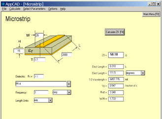
In the case of a micro-strip, the impedance will depend on 4 parameters:
- H is the height of the dielectric. It can be changed in steps. In this example +/- 1 mil results in +/- 2 ohms
- Er is the dielectric of the material. It is fixed once the material is chosen. Having a good idea of the Er is necessary since +/- 0.1 results in +/- 0.5 Ohms. To make things more complicated, only certain specialty materials like Rogers 4003 have well-defined dielectrics.
- T is the trace thickness. An outer trace is plated, providing a 20% uncertainty in exterior traces. This results in a small uncertainty of +/-0.2 ohms.
- W is the trace width. Typical trace width uncertainty is +/-2 mil which results in an uncertainty of +/- 2 ohms.
In the example provided, if the target impedance is 50 ohm, a 26 mil trace width is required. Since there is a tolerance on the input parameters it translates into a tolerance on the trace width. Achieving the calculated trace size should result in the required impedance.
A typical tolerance on final impedance is +/- 10%.
Achieving this requires a good understanding of the Er values and experience about how dielectric laminates behave. Ensure your PCB manufacturer has the knowledge and capabilities to meet your requirements. Specifying impedance control ensures you will need to work closer with your circuit board provider but the results are worth it.