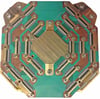
What is FR-4?
The short answer is "Yes," but there is a bit more to it.
What exactly is FR-4? FR-4 is a NEMA grade designation for flame-resistant glass-reinforced epoxy laminate. "FR" stands for Flame Retardant. The materials used are not defined by it, so different formulations can be rated FR-4. Unfortunately, it has become the norm in the industry to refer to the most commonly used PCB material by its FR-4 designation. As different formulations can share this rating, the properties of FR-4, particularly at cryogenic temperatures, can vary significantly.
With that clarification out of the way, we can tell you that we have been making FR-4 PCBs that our customers have been using reliably at cryogenic temperatures as low as 0.01 K (-273 °C or -459 °F), with repeated thermal cycles, for years and counting. However, this does not mean that we can use FR-4 can in all low-temperature applications (think millikelvin); other considerations must also be taken into account.
Differential Thermal Contraction
When we deal with room temperatures and above, a significant consideration is the coefficient of thermal expansion (CTE), which is typically treated as a constant. However, in cryogenics, the CTE changes with temperature and cannot be treated as a constant. At low temperatures, we are concerned with the differential thermal contraction between materials.
As a material is cooled, it contracts a certain amount that is determined by its thermal contraction curve, its length, and the change in temperature.
Differences in the materials within a printed circuit board or between the PCB and any part it's mounted to can result in differential thermal contraction that can cause significant stresses, component distortion in the case of an already populated PCB, and ultimately failure.
Take Away:
When you look for information on thermal coefficients, you will often find data that only applies to room temperature and above. The CTE is typically treated as a constant with temperature. For cryogenics, this is not the case. The contraction varies with temperature, and this must be considered.
Design Methods
While this post mainly covers differential contraction, other considerations must be taken into account in the design and material selection for cryogenic PCBs. Consider following Design For Excellence (DFX) methodologies, including Design For Manufacture and Assembly (DFMA), guidelines for which can be found in the IPC standards. We will be covering these methodologies in an upcoming post, so stay tuned and subscribe to the blog.
IPC, formerly called the "Institute for Interconnecting and Packaging Electronic Circuits," is the global trade association serving the printed board and electronics assembly industries, their customers and suppliers.
Although explaining how to kick-off your DFX analysis is beyond the scope of this post; we can tell you that historically three laminate properties of concern are:
- Out-of-plane and in-plane thermal contraction curves which will be different because of the composite structure of PCBs (in contrast to metals for which they are typically the same)
- Out-of-plane and in-plane coefficients of thermal expansion (CTE) which are often provided on technical datasheets (but are most accurately used for increasing temperature)
- Out-of-plane and in-plane stiffness or elastic modulus (E) which is rarely specified on technical datasheets and which typically require calculations based on in-plane laminate properties, glass fibre properties, glass fibre volume fraction, and the rule-of-mixtures
These material properties are determined by choice of resin, glass style, and filler.
What is G-10?
There are other candidate materials such as G-10 (which is similar to FR-4 but is not fire rated) and G-10 CR. G-10 CR is specially formulated to reduce the variability of its properties in cryogenic applications ("CR" stands for cryogenic). The properties of G-10 CR at these temperatures are more consistent and have been studied more closely than those of the more common FR-4 and other substrates.
For those of you who want to dig deeper, we can help you. We have many years of experience making boards that have operated reliably at cryogenic temperatures.
In the meantime, you can listen to this PCB Chat podcast, and we can point you to some of the tests methods developed by IPC to help you understand the thermal parameters of laminates:
- Glass transition temperature (Tg) and Z-Axis Thermal Expansion by TMA (Thermal Mechanical Analysis)
- IPC-TM-650, 2.4.24C & 2.4.25D - Characterizes complex material transformation like increase in CTE and a decrease in modulus
- Time to delamination
- IPC-TM-650, 2.4.24.1 - Characterizes interfacial adhesion
- Temperature of decomposition (Td)
- IPC-TM-650, 2.3.40 - Characterizes breakdown of epoxy material